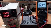


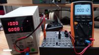
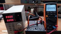
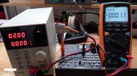
Many of you have asked us if the MATRIX II generates a voltage difference between its inputs and outputs?
Better than a thousand words, a few photos to demonstrate the performance.
Lab measurements
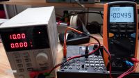
As voltage source, a laboratory linear power supply with an output impedance of a few milli-Ω.
As destination, a 40,000-point voltmeter with an impedance of 10 MΩ, with one probe connected to the MATRIX II's input 1 and the other to its output 1.
NB: For negative measurements, the red and black banana plugs are reversed on the power supply.
Results
The 5 photos show, in order, measurements at +10V, +2V, 0V, -5V and -10V, with differences of just a few mV, i.e. insignificant.
And in your Eurocase?
In your Eurocase, source and destination impedances depend on each manufacturer and are less favorable than in the laboratory.
Generally speaking, module outputs always have a series protection resistor of around 1 KΩ. However, some manufacturers, including Alyseum, compensate for the voltage drop in this resistor due to the load at the other end of the cable.
Module inputs have an impedance of around 100 KΩ.
Conclusions
In the laboratory, these measurements show insignificant differences between the input and output of a MATRIX II module.
In your Eurocase, it's the other modules that, on a case-by-case basis, are the main generators of voltage drift.
MATRIX II - Voltage tracking test.
Until 2022

My cart: % article(s)


2011-2099 © Alyseum.com - All rights reserved.
The ALYSEUM website does not contain any commercial or tracking cookies.
Informations and specifications described in this web site are subject to change without notice